Abstrak
Intrusion Detection System
digunakan untuk mendeteksi aktivitas yang mencurigakan dalam sebuah sistem atau
jaringan. Intrusion adalah aktivitas tidak sah atau tidak diinginkan yang
mengganggu konfidensialitas, integritas dan atau ketersediaan dari informasi
yang terdapat di sebuah sistem. IDS akan memonitor lalu lintas data pada sebuah
jaringan atau mengambil data dari berkas log. IDS akan menganalisa dan dengan
algoritma tertentu akan memutuskan untuk memberi peringatan kepada seorang
administrator jaringan atau tidak
Keywords : intrusion, intrusion detection system, jaringan, network security
Keywords : intrusion, intrusion detection system, jaringan, network security

Contoh Perangkat Dengan IDS
Cisco IDE 4200 Series Ids-4215-K9 Intrusion Detection Sensor


Wireless LAN Controller and IPS Integration Guide
Introduction
The Cisco Unified Intrusion Detection System (IDS)/Intrusion Prevention System (IPS) is part of the Cisco Self-Defending Network and is the first integrated wired and wireless security solution in the industry. The Cisco Unified IDS/IPS takes a comprehensive approach to security—at the wireless edge, wired edge, WAN edge, and through the data center. When an associated client sends malicious traffic through the Cisco Unified Wireless Network, a Cisco wired IDS device detects the attack and sends shun requests to Cisco Wireless LAN Controllers (WLCs), which then disassociate the client device.The Cisco IPS is an inline, network-based solution, designed to accurately identify, classify, and stop malicious traffic, including worms, spyware / adware, network viruses, and application abuse, before they affect business continuity.
With the utilization of Cisco IPS Sensor software version 5, the Cisco IPS solution combines inline prevention services with innovative technologies to improve accuracy. The result is total confidence in the provided protection of your IPS solution, without the fear of legitimate traffic being dropped. The Cisco IPS solution also offers comprehensive protection of your network through its unique ability to collaborate with other network security resources and provides a proactive approach to the protection of your network.
The Cisco IPS solution helps users stop more threats with greater confidence through the use of these features:
- Accurate inline prevention technologies—Provides
unparalleled confidence to take preventive action against a broader
range of threats without the risk of dropping legitimate traffic. These
unique technologies offer intelligent, automated, contextual analysis of
your data and help ensure that you receive the most out of your
intrusion prevention solution.
- Multi-vector threat identification—Protects your
network from policy violations, vulnerability exploitations, and
anomalous activity through detailed inspection of traffic in Layers 2
through 7.
- Unique network collaboration—Enhances scalability
and resiliency through network collaboration, including efficient
traffic capture techniques, load-balancing capabilities, and visibility
into encrypted traffic.
- Comprehensive deployment solutions—Provides
solutions for all environments, from small and medium-sized businesses
(SMBs) and branch office locations to large enterprise and service
provider installations.
- Powerful management, event correlation, and support services—Enables
a complete solution, including configuration, management, data
correlation, and advanced support services. In particular the Cisco
Security Monitoring, Analysis, and Response System (MARS) identifies,
isolates, and recommends precision removal of offending elements, for a
network wide intrusion prevention solution. And the Cisco Incident
Control System prevents new worm and virus outbreaks by enabling the
network to rapidly adapt and provide a distributed response.
Prerequisites
Requirements
Ensure that you meet these minimum requirements:- WLC firmware version 4.x and later
- Knowledge on how to configure Cisco IPS and the Cisco WLC is desirable.
Components Used
Cisco WLCThese controllers are included with software release 4.0 for IDS modifications:
- Cisco 2000 Series WLC
- Cisco 2100 Series WLC
- Cisco 4400 Series WLC
- Cisco Wireless Services Module (WiSM)
- Cisco Catalyst 3750G Series Unified Access Switch
- Cisco Wireless LAN Controller Module (WLCM)
- Cisco Aironet 1100 AG Series Lightweight Access Points
- Cisco Aironet 1200 AG Series Lightweight Access Points
- Cisco Aironet 1300 Series Lightweight Access Points
- Cisco Aironet 1000 Series Lightweight Access Points
- Cisco Wireless Control System (WCS)
- Cisco 4200 Series Sensor
- Cisco IDS Management - Cisco IDS Device Manager (IDM)
- Cisco IPS 4200 Series Sensors with Cisco IPS Sensor Software 5.x or later.
- SSM10 and SSM20 for the Cisco ASA 5500 Series Adaptive Security Appliances with Cisco IPS Sensor Software 5.x
- Cisco ASA 5500 Series Adaptive Security Appliances with Cisco IPS Sensor Software 5.x
- Cisco IDS Network Module (NM-CIDS) with Cisco IPS Sensor Software 5.x
- Cisco Catalyst 6500 Series Intrusion Detection System Module 2 (IDSM-2) with Cisco IPS Sensor Software 5.x
Conventions
Refer to Cisco Technical Tips Conventions for more information on document conventions.Cisco IDS Overview
The major components of the Cisco IDS (Version 5.0) are:- Sensor App—Performs packet capture and analysis.
- Event Storage Management and Actions Module—Provides storage of policy violations.
- Imaging, Install and Startup Module—Loads, initializes, and starts all the system software.
- User Interfaces and UI Support Module—Provides an embedded CLI and the IDM.
- Sensor OS—Host operating system (based on Linux).
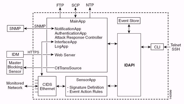
The Sensor Application (IPS software) consists of:
- Main App—Initializes the system, starts and stops
other applications, configures the OS and is responsible for upgrades.
It contains these components:
- Control Transaction Server—Allows the Sensors to
send control transactions which are used to enable the Attack Response
Controller (formerly known as Network Access Controller) Master Blocking
Sensor capability.
- Event Store—An indexed store used to store IPS
events (errors, status and alert system messages) that is accessible
through the CLI, IDM, Adaptive Security Device Manager (ASDM), or Remote
Data Exchange Protocol (RDEP).
- Control Transaction Server—Allows the Sensors to
send control transactions which are used to enable the Attack Response
Controller (formerly known as Network Access Controller) Master Blocking
Sensor capability.
- Interface App—Handles bypass and physical settings
and defines paired interfaces. Physical settings consist of speed,
duplex, and administrative states.
- Log App—Writes the log messages of the application to the log file and the error messages to the Event Store.
- Attack Response Controller (ARC) (formerly known as Network Access Controller)—Manages
remote network devices (firewalls, routers, and switches) to provide
blocking capabilities when an alert event has occurred. ARC creates and
applies access control lists (ACLs) on the controlled network device or
uses the shun command (firewalls).
- Notification App—Sends SNMP traps when triggered by
an alert, status, and error events. The Notification App uses a public
domain SNMP agent in order to this. The SNMP GETs provide information
about the health of a Sensor.
- Web Server (HTTP RDEP2 server)—Provides a web user
interface. It also provides a means to communicate with other IPS
devices through RDEP2 using several servlets to provide IPS services.
- Authentication App—Verifies that users are authorized to perform CLI, IDM, ASDM, or RDEP actions.
- Web Server (HTTP RDEP2 server)—Provides a web user
interface. It also provides a means to communicate with other IPS
devices through RDEP2 using several servlets to provide IPS services.
- Sensor App (Analysis Engine)—Performs packet capture and analysis.
- CLI—The interface that is run when users
successfully log in to the Sensor through Telnet or SSH. All accounts
created through the CLI use the CLI as their shell (except the service
account - only one service account is allowed). Allowed CLI commands
depend on the privilege of the user.
It must be noted that the Sensor has these disk partitions:
- Application Partition—Contains the full IPS system image.
- Maintenance Partition—A special purpose IPS image
used to re-image the application partition of the IDSM-2. A re-image of
the maintenance partition results in lost configuration settings.
- Recovery Partition—A special purpose image used for
recovery of the Sensor. Booting into the recovery partition enables
users to completely re-image the application partition. Network settings
are preserved, but all other configurations are lost.
Cisco IDS and WLC – Integration Overview
Version 5.0 of the Cisco IDS introduces the ability to configure deny actions when policy violations (signatures) are detected. Based on user configuration at the IDS/IPS system, a shun request can be sent to a firewall, router, or WLC in order to block the packets from a particular IP address.With the Cisco Unified Wireless Network Software Release 4.0 for Cisco Wireless Controllers, a shun request needs to be sent to a WLC in order to trigger the client blacklisting or exclusion behavior available on a controller. The interface the controller uses to get the shun request is the command and control interface on the Cisco IDS.
- The controller allows up to five IDS Sensors to be configured on a given controller.
- Each configured IDS Sensor is identified by its IP address or qualified network name and authorization credentials.
- Each IDS Sensor can be configured on a controller with a unique query rate in seconds.
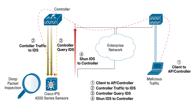
IDS Shunning
The controller queries the Sensor at the configured query rate in order to retrieve all the shun events. A given shun request is distributed throughout the entire mobility group of the controller that retrieves the request from the IDS Sensor. Each shun request for a client IP address is in effect for the specified timeout seconds value. If the timeout value indicates an infinite time, then the shun event ends only if the shun entry is removed on the IDS. The shunned client status is maintained on each controller in the mobility group even if any or all of the controllers are reset.Note: The decision to shun a client is always made by the IDS Sensor. The controller does not detect Layer 3 attacks. It is a far more complicated process to determine that the client is launching a malicious attack at Layer 3. The client is authenticated at Layer 2 which is good enough for the controller to grant Layer 2 access.
Note: For example, if a client gets a previous offending (shunned) IP address assigned, it is up to the Sensor timeout to unblock the Layer 2 access for this new client. Even if the controller gives access at Layer 2, the client traffic might be blocked at routers in Layer 3 anyway, because the Sensor also informs routers of the shun event.
Assume that a client has IP address A. Now, when the controller polls the IDS for shun events, the IDS sends the shun request to the controller with IP address A as the target IP address. Now, the controller black lists this client A. On the controller, clients are disabled based on a MAC address.
Now, assume that the client changes its IP address from A to B. During the next poll, the controller gets a list of shunned clients based on IP address. This time again, IP address A is still in the shunned list. But since the client has changed its IP address from A to B (which is not in the shunned list of IP addresses), this client with a new IP address of B is released once the timeout of black listed clients is reached on the controller. Now, the controller starts to allow this client with new the IP address of B (but the client MAC address remains the same).
Therefore, although a client remains disabled for the duration of the controller exclusion time and is re-excluded if it re-acquires its previous DHCP address, that client is no longer disabled if the IP address of the client that is shunned changes. For example, if the client connects to the same network and the DHCP lease timeout is not expired.
Controllers only support connection to the IDS for client shunning requests that use the management port on the controller. The controller connects to the IDS for packet inspection via the applicable VLAN interfaces that carry wireless client traffic.
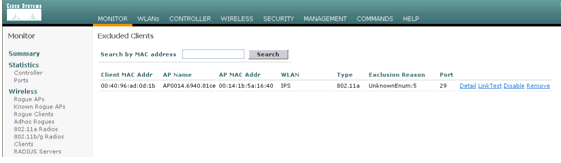
On the controller, the Disable Clients page shows each client that has been disabled via an IDS Sensor request. The CLI show command also displays a list of blacklisted clients.
On the WCS, the excluded clients are displayed under the Security sub tab.
Here are the steps to follow in order to complete the integration of Cisco IPS Sensors and Cisco WLCs.
- Install and connect the IDS appliance on the same switch where the wireless controller resides.
- Mirror (SPAN) the WLC ports that carry the wireless client traffic to the IDS appliance.
- The IDS appliance receives a copy of every packet and inspects traffic at Layer 3 through 7.
- The IDS appliance offers a downloadable signature file, which can also be customized.
- The IDS appliance generates the alarm with an event action of shun when an attack signature is detected.
- The WLC polls the IDS for alarms.
- When an alarm with the IP address of a wireless client,
which is associated to the WLC, is detected, it puts the client into the
exclusion list.
- A trap is generated by the WLC and WCS is notified.
- The user is removed from the exclusion list after the specified time period.
Network Architecture Design
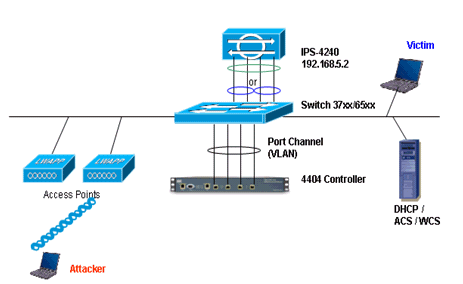
The Cisco WLC is connected to the gigabit interfaces on the Catalyst 6500. Create a port-channel for the gigabit interfaces and enable Link Aggregation (LAG) on the WLC.
The controller is connected to interface gigabit 5/1 and gigabit 5/2 on the Catalyst 6500.(Cisco Controller) >show interface summary Interface Name Port Vlan Id IP Address Type Ap Mgr -------------------------------- ---- -------- --------------- ------- ------ ap-manager LAG untagged 10.10.99.3 Static Yes management LAG untagged 10.10.99.2 Static No service-port N/A N/A 192.168.1.1 Static No virtual N/A N/A 1.1.1.1 Static No vlan101 LAG 101 10.10.101.5 Dynamic No
The sensing interfaces of the IPS Sensor can operate individually in Promiscuous mode or you can pair them to create inline interfaces for Inline Sensing mode.cat6506#show run interface gigabit 5/1 Building configuration... Current configuration : 183 bytes ! interface GigabitEthernet5/1 switchport switchport trunk encapsulation dot1q switchport trunk native vlan 99 switchport mode trunk no ip address channel-group 99 mode on end cat6506#show run interface gigabit 5/2 Building configuration... Current configuration : 183 bytes ! interface GigabitEthernet5/2 switchport switchport trunk encapsulation dot1q switchport trunk native vlan 99 switchport mode trunk no ip address channel-group 99 mode on end cat6506#show run interface port-channel 99 Building configuration... Current configuration : 153 bytes ! interface Port-channel99 switchport switchport trunk encapsulation dot1q switchport trunk native vlan 99 switchport mode trunk no ip address end
In Promiscuous mode, packets do not flow through the Sensor. The Sensor analyzes a copy of the monitored traffic rather than the actual forwarded packet. The advantage of operating in Promiscuous mode is that the Sensor does not affect the packet flow with the forwarded traffic.
Note: The architecture diagram is just an example setup of WLC and IPS integrated architecture. The example configuration shown here explains the IDS sensing interface acting in Promiscuous mode. The architecture diagram shows the sensing interfaces being paired together to act in Inline Pair mode. Refer to Inline Mode for more information about Inline Interface mode.
In this configuration, it is assumed that the sensing interface acts in Promiscuous mode. The monitoring interface of the Cisco IDS Sensor is connected to the gigabit interface 5/3 on the Catalyst 6500. Create a monitor session on the Catalyst 6500 where the port-channel interface is the source of the packets and the destination is the gigabit interface where the monitoring interface of the Cisco IPS Sensor is connected. This replicates all ingress and egress traffic from the controller wired interfaces to the IDS for Layer 3 through Layer 7 inspection.
cat6506#show run | inc monitor
monitor session 5 source interface Po99
monitor session 5 destination interface Gi5/3

cat6506#show monitor session 5
Session 5
---------
Type                   : Local Session
Source Ports           :
    Both               : Po99
Destination Ports      : Gi5/3
cat6506#
Configure the Cisco IDS Sensor
The initial configuration of the Cisco IDS Sensor is done from the console port or by connecting a monitor and keyboard to the Sensor.- Log in to the appliance:
- Connect a console port to the Sensor.
- Connect a monitor and a keyboard to the Sensor.
- Connect a console port to the Sensor.
- Type your username and password at the login prompt.
Note: The default username and password are both cisco. You are prompted to change them the first time you log in to the appliance. You must first enter the UNIX password, which is cisco. Then you must enter the new password twice.
login: cisco
Password:
***NOTICE***
This product contains cryptographic features and is subject to
United States and local country laws governing import, export,
transfer and use. Delivery of Cisco cryptographic products does
not imply third-party authority to import, export, distribute or
use encryption. importers, exporters, distributors and users are
responsible for compliance with U.S. and local country laws.
By using this product you agree to comply with applicable laws
and regulations. If you are unable to comply with U.S. and local laws,
return this product immediately.

A summary of U.S. laws governing Cisco cryptographic products may
be found at:

http://www.cisco.com/wwl/export/crypto/tool/stqrg.html

If you require further assistance please contact us by sending
email to export@cisco.com.
***LICENSE NOTICE***
There is no license key installed on the system.
Please go to https://tools.cisco.com/SWIFT/Licensing/PrivateRegistrationServlet
           (registered customers only)

to obtain a new license or install a license.
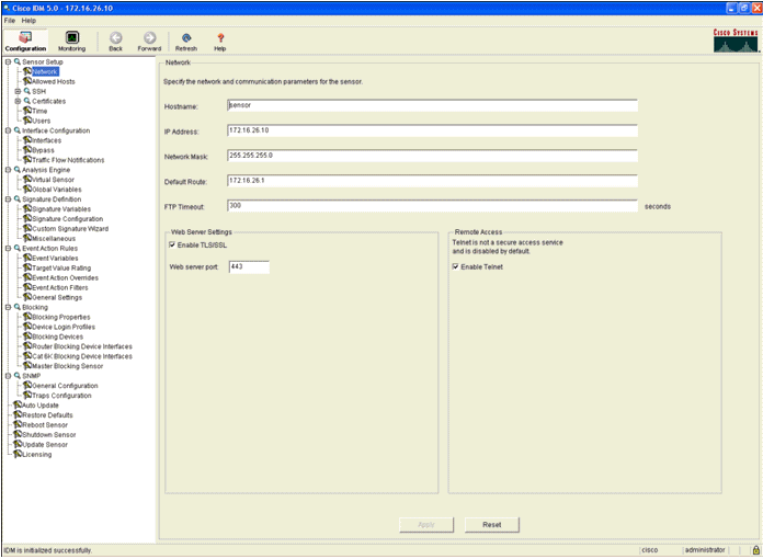
- Configure the IP address, subnet mask and access list on the Sensor.
Note: This is the command and control interface on the IDS used to communicate with the controller. This address should be routable to the controller management interface. The sensing interfaces do not require addressing. The access list should include the controller(s) management interface address, as well as allowable addresses for management of the IDS.
sensor#configure terminal
sensor(config)#service host
sensor(config-hos)#network-settings
sensor(config-hos-net)#host-ip 192.168.5.2/24,192.168.5.1
sensor(config-hos-net)#access-list 10.0.0.0/8
sensor(config-hos-net)#access-list 40.0.0.0/8
sensor(config-hos-net)#telnet-option enabled
sensor(config-hos-net)#exit
sensor(config-hos)#exit
Apply Changes:?[yes]: yes
sensor(config)#exit
sensor#
sensor#ping 192.168.5.1
PING 192.168.5.1 (192.168.5.1): 56 data bytes
64 bytes from 192.168.5.1: icmp_seq=0 ttl=255 time=0.3 ms
64 bytes from 192.168.5.1: icmp_seq=1 ttl=255 time=0.9 ms
64 bytes from 192.168.5.1: icmp_seq=2 ttl=255 time=0.3 ms
64 bytes from 192.168.5.1: icmp_seq=3 ttl=255 time=1.0 ms
--- 192.168.5.1 ping statistics ---
4 packets transmitted, 4 packets received, 0% packet loss
round-trip min/avg/max = 0.3/0.6/1.0 ms
sensor#
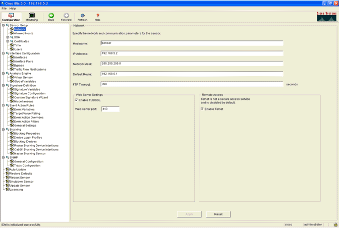
- You can now configure the IPS Sensor from the GUI. Point the
browser to the management IP address of the Sensor. This image displays
a sample where the Sensor is configured with 192.168.5.2..
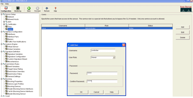
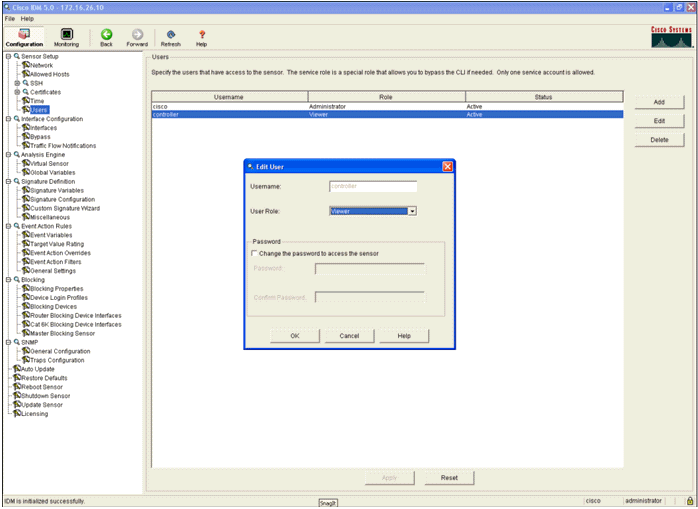
- Add a user that the WLC uses to access the IPS Sensor events.
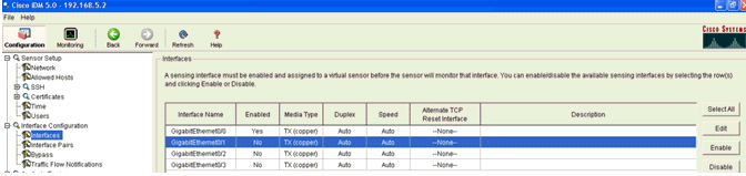
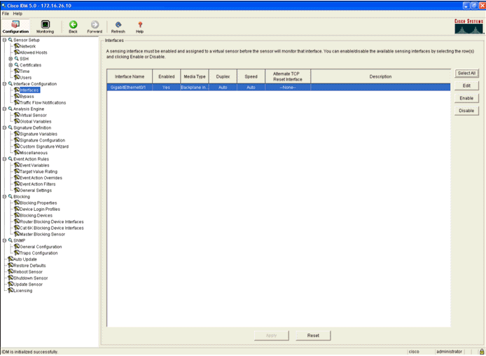
- Enable the monitoring interfaces.
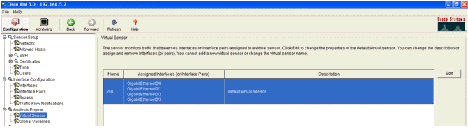
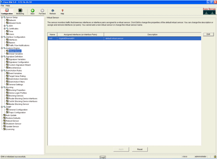
The monitoring interfaces must be added to the Analysis Engine, as this window shows:
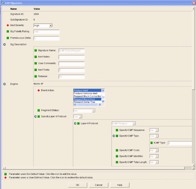
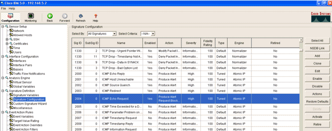
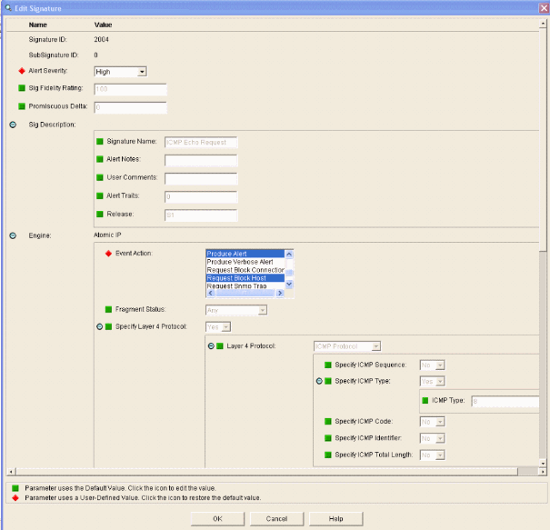
- Select the 2004 signature (ICMP Echo Request) in order to perform a quick setup verification.

The signature should be enabled, Alert Severity set to High and Event Action set to Produce Alert and Request Block Host for this verification step to be completed.
Configure the WLC
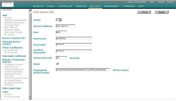
Complete these steps in order to configure the WLC:- Once the IPS appliance is configured and ready to be added in the controller, choose Security > CIDS > Sensors > New.
- Add the IP address, TCP port number, username and password you previously created.
In order to obtain the fingerprint from the IPS Sensor, execute this command in the IPS Sensor and add the SHA1 fingerprint on the WLC (without the colon). This is used to secure the controller-to-IDS polling communication.
sensor#show tls fingerprint
MD5: 1A:C4:FE:84:15:78:B7:17:48:74:97:EE:7E:E4:2F:19
SHA1: 16:62:E9:96:36:2A:9A:1E:F0:8B:99:A7:C1:64:5F:5C:B5:6A:88:42
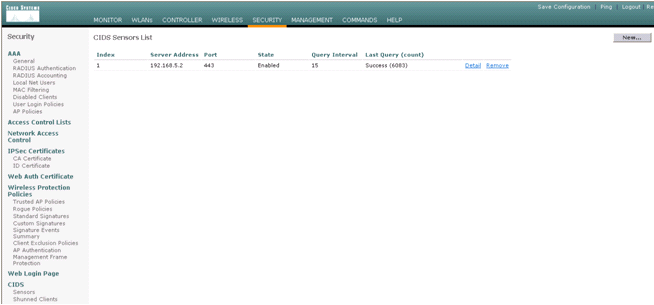
- Check the status of the connection between the IPS Sensor and the WLC.
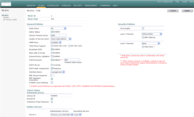
- Once you establish the connectivity with the Cisco IPS Sensor, make sure the WLAN configuration is correct and that you enable Client Exclusion.
The default client exclusion timeout value is 60 seconds. Also note that regardless of the client exclusion timer, the client exclusion persists as long as the client block invoked by the IDS remains active. The default block time in the IDS is 30 minutes.
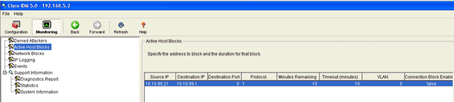
- You can trigger an event in the Cisco IPS system either when
you do an NMAP Scan to certain devices in the network or when you do a
ping to some hosts monitored by the Cisco IPS Sensor. Once an alarm is
triggered in the Cisco IPS, go to Monitoring and Active Host Blocks in order to check the details about the host.
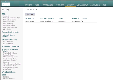
The Shunned Clients list in the controller is now populated with the IP and MAC address of the host.
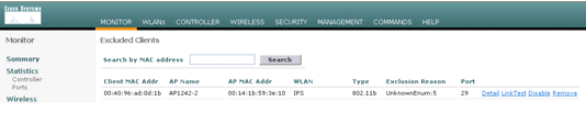
The user is added to the Client Exclusion list.
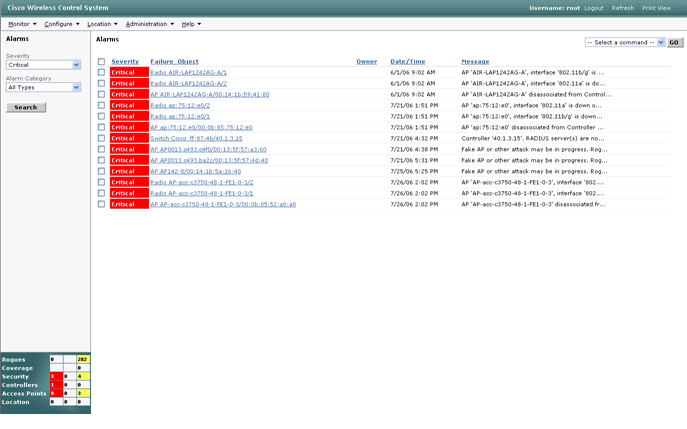
A trap log is generated as a client is added to the shun list.
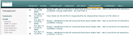
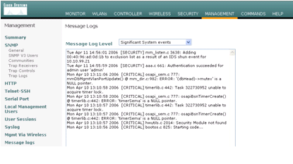
A message log is also generated for the event.
Some additional events are generated in the Cisco IPS Sensor when an NMAP scan is done on a device it monitors.
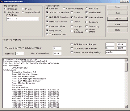
This window shows events generated in the Cisco IPS Sensor.
Cisco IDS Sensor Sample Configuration
This is the output from the setup script from the installation:sensor#show config ! ------------------------------ ! Version 5.0(2) ! Current configuration last modified Mon Apr 03 15:32:07 2006 ! ------------------------------ service host network-settings host-ip 192.168.5.2/25,192.168.5.1 host-name sensor telnet-option enabled access-list 10.0.0.0/8 access-list 40.0.0.0/8 exit time-zone-settings offset 0 standard-time-zone-name UTC exit exit ! ------------------------------ service notification exit ! ------------------------------ service signature-definition sig0 signatures 2000 0 alert-severity high status enabled true exit exit signatures 2001 0 alert-severity high status enabled true exit exit signatures 2002 0 alert-severity high status enabled true exit exit signatures 2003 0 alert-severity high status enabled true exit exit signatures 2004 0 alert-severity high engine atomic-ip event-action produce-alert|request-block-host exit status enabled true exit exit exit ! ------------------------------ service event-action-rules rules0 exit ! ------------------------------ service logger exit ! ------------------------------ service network-access exit ! ------------------------------ service authentication exit ! ------------------------------ service web-server exit ! ------------------------------ service ssh-known-hosts exit ! ------------------------------ service analysis-engine virtual-sensor vs0 description default virtual sensor physical-interface GigabitEthernet0/0 exit exit ! ------------------------------ service interface physical-interfaces GigabitEthernet0/0 admin-state enabled exit exit ! ------------------------------ service trusted-certificates exit sensor#
Configure an ASA for IDS
Unlike a traditional Intrusion Detection Sensor, an ASA must always be in the data path. In other words, instead of spanning traffic from a switch port over to a passive sniffing port on the Sensor, the ASA must receive data on one interface, process it internally, and then forward it out another port. For IDS, use the modular policy framework (MPF) in order to copy traffic the ASA receives over to the internal Advanced Inspection and Prevention Security Services Module (AIP-SSM) for inspection.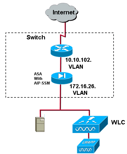
In this example, the ASA used is already setup and passes traffic. These steps demonstrate how to create a policy that sends data to the AIP-SSM.
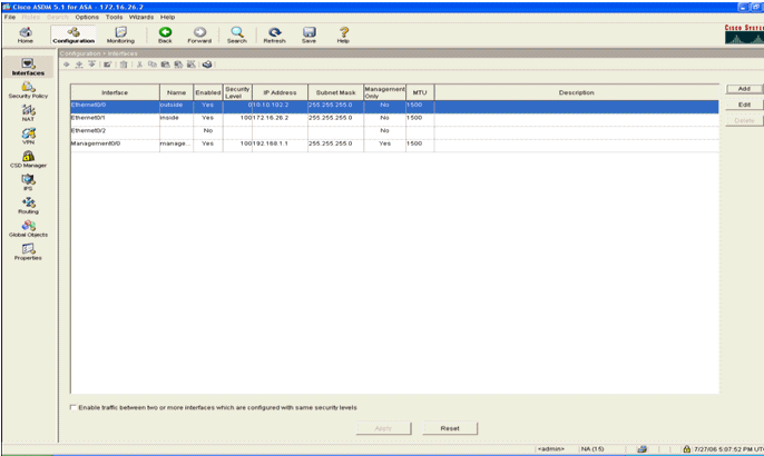
- Log into the ASA using ASDM. Upon successful login, the ASA Main System window appears.
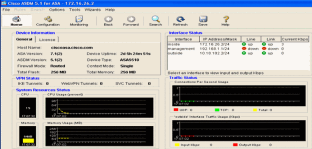
- Click Configuration at the top of the page. The window switches to a view of the ASA interfaces.
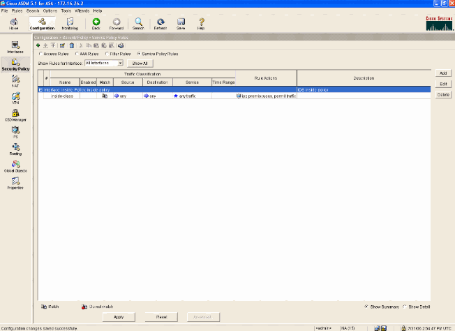
- Click Security Policy on the left-hand side of the window. On the resultant window, choose the Service Policy Rules tab.
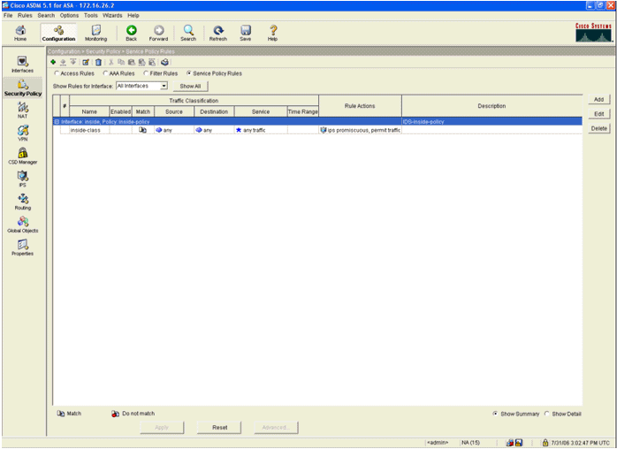
- Click Add in order to create a new policy. The Add Service Policy Rule Wizard launches in a new window.
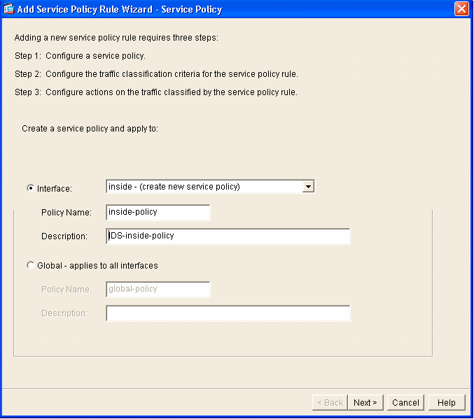
- Click Interface and then choose the correct
interface from the drop-down list in order to create a new policy which
is bound to one of the interfaces that passes traffic.
- Give the policy a name and a description of what the policy does using the two text boxes.
- Click Next in order to move to the next step.
- Click Interface and then choose the correct
interface from the drop-down list in order to create a new policy which
is bound to one of the interfaces that passes traffic.
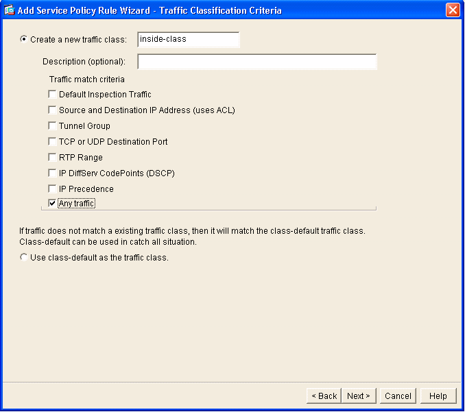
- Build a new traffic class to apply to the policy.
It is reasonable to build specific classes in order to inspect specific data types, but in this example, Any Traffic is selected for simplicity. Click Next in order to proceed.
- Complete these steps in order to
instruct the ASA to direct the traffic over to its AIP-SSM.
- Check Enable IPS for this traffic flow in order to enable intrusion detection.
- Set the mode to Promiscuous so that a copy of the traffic is sent to the module out-of-band instead of placing the module inline with the data flow.
- Click Permit traffic in order to ensure that the ASA switches to a fail-open state in the event that the AIP-SSM fails.
- Click Finish in order to commit the change.
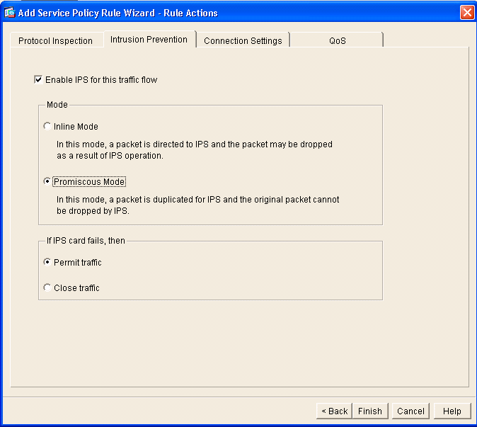
- Check Enable IPS for this traffic flow in order to enable intrusion detection.
- The ASA is now configured to send traffic to the IPS module. Click Save on the top row in order to write the changes to the ASA.
Configure the AIP-SSM for Traffic Inspection
While the ASA sends data to the IPS module, associate the AIP-SSM interface to its virtual Sensor engine.- Login to the AIP-SSM using IDM.
- Add a user with at least viewer privileges.
- Enable the interface.
- Check the Virtual Sensor configuration.
Configure a WLC to Poll the AIP-SSM for Client Blocks
Complete these steps once the Sensor is configured and ready to be added in the controller:- Choose Security > CIDS > Sensors > New in the WLC.
- Add the IP address, TCP port number, username and password you created in the previous section.
- In order to obtain the fingerprint from the Sensor, execute
this command in the Sensor and add the SHA1 fingerprint on the WLC
(without the colon). This is used to secure the controller-to-IDS
polling communication.
sensor#show tls fingerprint
MD5: 07:7F:E7:91:00:46:7F:BF:11:E2:63:68:E5:74:31:0E
SHA1: 98:C9:96:9B:4E:FA:74:F8:52:80:92:BB:BC:48:3C:45:B4:87:6C:55
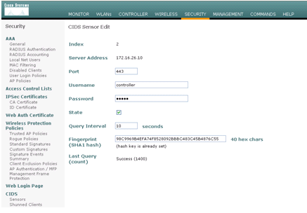
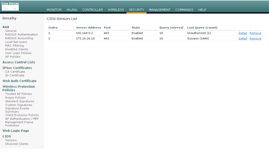
- Check the status of the connection between the AIP-SSM and the WLC.
Add a Blocking Signature to the AIP-SSM
Add an inspection signature to block traffic. Although there are many signatures that can do the job based on the tools available, this example creates a signature that blocks ping packets.- Select the 2004 signature (ICMP Echo Request) in order to perform a quick setup verification.
- Enable the signature, set the Alert Severity to High and set Event Action to Produce Alert and Request Block Host
in order to complete this verification step. Note that the Request
Block Host action is the key to signaling the WLC to create client
exceptions.
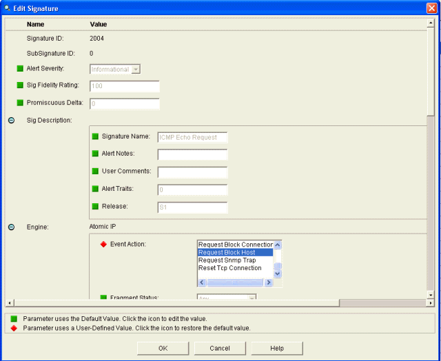
- Click OK in order to save the signature.
- Verify that the signature is active and that it is set to perform a blocking action.
- Click Apply in order to commit the signature to the module.
Monitor Blocking and Events with IDM
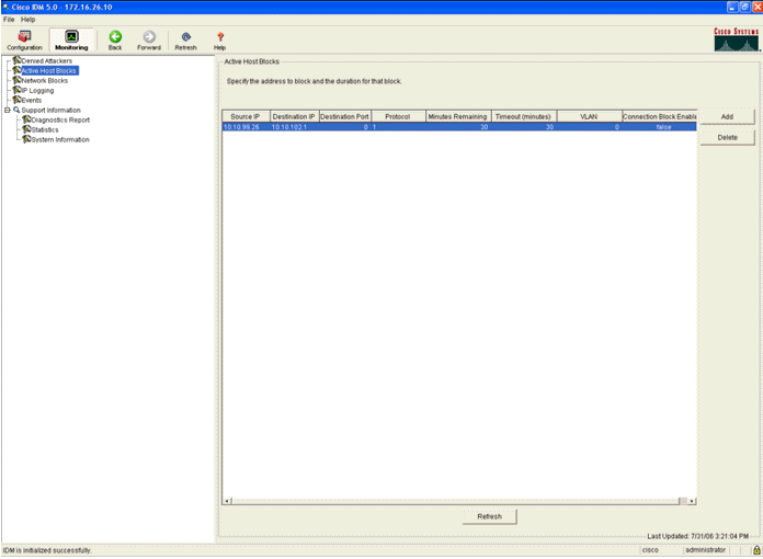
Complete these steps:- When the signature fires successfully, there are two places within IDM to note this.
The first method shows the active blocks that the AIP-SSM has installed. Click Monitoring along the top row of actions. Within the list of items that appears on the left-hand side, select Active Host Blocks. Whenever the ping signature triggers, the Active Host Blocks window shows the IP address of the offender, the address of the device under attack, and the time that remains for which the block is in effect. The default blocking time is 30 minutes and is tunable. However, changing this value is not discussed in this document. Consult the ASA configuration documentation as necessary for information on how to change this parameter. Remove the block immediately, select it from the list and then click Delete.
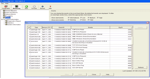
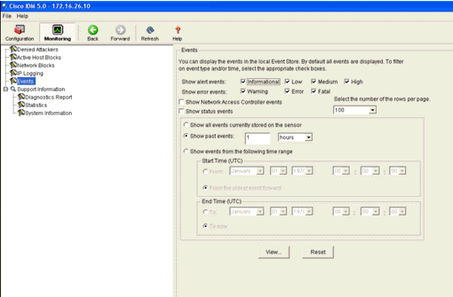
The second method to view triggered signatures uses the AIP-SSM event buffer. From the IDM Monitoring page, select Events in the items list on the left-hand side. The Events search utility appears. Set appropriate search criteria and click View....
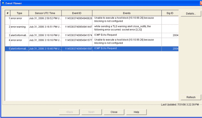
- The Event Viewer then appears with a list of events that
match the criteria given. Scroll through the list and find the ICMP Echo
Request signature modified in the previous configuration steps.
Look in the Events column for the name of the signature, or else search for the identification number of the signature under the Sig ID column.
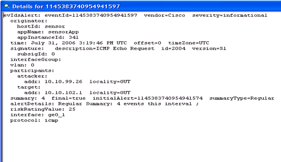
- After you locate the signature, double-click the entry in
order to open a new window. The new window contains detailed information
on the event that triggered the signature.
Monitor Client Exclusion in a Wireless Controller
The Shunned Clients list in the controller is populated at this point of time with the IP and MAC address of the host.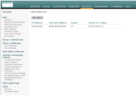
The user is added to the Client Exclusion list.
Monitor Events in WCS
Security events that trigger a block within the AIP-SSM cause the controller to add the address of the offender to the client exclusion list. An event is also generated within WCS.- Use the Monitor > Alarms utility from the WCS main
menu in order to view the exclusion event. WCS initially displays all
uncleared alarms and also presents a searching function on the left-hand
side of the window.
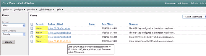
- Modify the search criteria to find the client block. Under Severity, choose Minor, and also set the Alarm Category to Security.
- Click Search.
- The Alarm window then lists only security alarms with minor
severity. Point the mouse at the event that triggered the block within
the AIP-SSM.
In particular, WCS shows the MAC address of the client station that caused the alarm. By pointing at the appropriate address, WCS pops-up a small window with the event details. Click the link in order to view these same details on another window.
Cisco ASA Sample Configuration
ciscoasa#show run
: Saved
:
ASA Version 7.1(2)
!
hostname ciscoasa
domain-name cisco.com
enable password 2KFQnbNIdI.2KYOU encrypted
names
!
interface Ethernet0/0
 nameif outside
 security-level 0
 ip address 10.10.102.2 255.255.255.0
!
interface Ethernet0/1
 nameif inside
 security-level 100
 ip address 172.16.26.2 255.255.255.0
!
interface Ethernet0/2
 shutdown
 no nameif
 no security-level
 no ip address
!
interface Management0/0
 nameif management
 security-level 100
 ip address 192.168.1.1 255.255.255.0
 management-only
!
passwd 2KFQnbNIdI.2KYOU encrypted
ftp mode passive
dns server-group DefaultDNS
 domain-name cisco.com
pager lines 24
logging asdm informational
mtu inside 1500
mtu management 1500
mtu outside 1500
asdm image disk0:/asdm512-k8.bin
no asdm history enable
arp timeout 14400
nat-control
global (outside) 102 interface
nat (inside) 102 172.16.26.0 255.255.255.0
nat (inside) 102 0.0.0.0 0.0.0.0
route inside 0.0.0.0 0.0.0.0 172.16.26.1 1
timeout xlate 3:00:00
timeout conn 1:00:00 half-closed 0:10:00 udp 0:02:00 icmp 0:00:02
timeout sunrpc 0:10:00 h323 0:05:00 h225 1:00:00 mgcp 0:05:00
timeout mgcp-pat 0:05:00 sip 0:30:00 sip_media 0:02:00
timeout uauth 0:05:00 absolute
http server enable
http 10.1.1.12 255.255.255.255 inside
http 0.0.0.0 0.0.0.0 inside
http 192.168.1.0 255.255.255.0 management
no snmp-server location
no snmp-server contact
snmp-server enable traps snmp authentication linkup linkdown coldstart
telnet 0.0.0.0 0.0.0.0 inside
telnet timeout 5
ssh timeout 5
console timeout 0
dhcpd address 192.168.1.2-192.168.1.254 management
dhcpd lease 3600
dhcpd ping_timeout 50
dhcpd enable management
!
class-map inside-class
 match any
!
!
policy-map inside-policy
 description IDS-inside-policy
 class inside-class
  ips promiscuous fail-open
!
service-policy inside-policy interface inside
Cryptochecksum:699d110f988e006f6c5c907473939b29
: end
ciscoasa#
Cisco Intrusion Prevention System Sensor Sample Configuration
sensor#show config
! ------------------------------
! Version 5.0(2)
! Current configuration last modified Tue Jul 25 12:15:19 2006
! ------------------------------
service host
network-settings
host-ip 172.16.26.10/24,172.16.26.1
telnet-option enabled
access-list 10.0.0.0/8
access-list 40.0.0.0/8
exit
exit
! ------------------------------
service notification
exit
! ------------------------------
service signature-definition sig0
signatures 2004 0
engine atomic-ip
event-action produce-alert|request-block-host
exit
status
enabled true
exit
exit
exit
! ------------------------------
service event-action-rules rules0
exit
! ------------------------------
service logger
exit
! ------------------------------
service network-access
exit
! ------------------------------
service authentication
exit
! ------------------------------
service web-server
exit
! ------------------------------
service ssh-known-hosts
exit
! ------------------------------
service analysis-engine
virtual-sensor vs0
description default virtual sensor
physical-interface GigabitEthernet0/1
exit
exit
! ------------------------------
service interface
exit
! ------------------------------
service trusted-certificates
exit
sensor#
Verify
There is currently no verification procedure available for this configuration.Troubleshoot
There is currently no specific troubleshooting information available for this configuration.Sumber
https://www.cisco.com/c/en/us/support/docs/wireless-mobility/wlan-security/71231-wlc-ips-integration-guide.html
https://picclick.com/Cisco-IDS-4215-K9-IDS-4200-Series-Sensor-Intrusion-Detection-390812870966.html
Tidak ada komentar:
Posting Komentar